BMW Luxury Touring Community banner
61 - 80 of 143 Posts
Great, I got it all. Now I have to try to fix mine.
I collected 5 ABS 3 units.- 3 from BMW 1150 and 2 from k1200 LT, I'm not going to run out of parts, I have work for this winter.
In the meantime I ordered an emulator in Poland and I will mount it on my motorbike. I will give you my impressions.
Hi, hope your work went well and your unit works. I have problem with K12LT 2008 and most probably need the circuit board. Would you sell it to me at a reasonable price if it works?
Also intressted in P sensors if available.
Thank you very much
Farugh
 
Hi Chris,

You can use a lot of the internal parts between the various models except for these 3 things which are specifics to each model (K1200LT, K1200RS/GT, R1150RT ....):

1/ The electronic board is specific to the model

2/ The pressure relief valve is colour coded. Even on the same model, the front and the rear units are sometimes different. I have seen blue, yellow, white, green colour dot on the top of the black cap.
These valves are used to stabilize the pressure created by the pilot when the brake lever is pulled.

View attachment 175268

3/ The integral piston located in the first section of the unit. It depends if it is an Integral ABS or a Semi-Integral ABS.

View attachment 175269


As long as you can order the correct seals (FPM) and replace all of them, and the capability to check the 4 internal pressure sensors (GS911 can do it), you might be able to rebuild a working unit.
These pressure sensors and the DC motors are the most problematic parts.
Some components on the main board can die, due to a problem with one or the 2 DC motors but it is more or less an easy fix.

Good luck,
Thanks for the invaluable information. I guess my problem is in the circuit board, showing signes of sporadic short circuit (It can not communicate with engine control unit).
You mentioned main board could be an easy fix. Where should I look for what to replace. Don't see any blown capacitors or burned components.
Thanks for all kind of hints and suggestions.
Kind regards
Farugh
 
Hello,

Before to try to repair, you must have a tool which can diagnose the system. It can be a GS911 or a ISTA D system. There are valuable tools that can give you information about what is faulty in the unit itself. Specially for the Pressure Sensors which are the most problematic parts to replace due to unavailable spare.

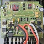
For the circuit board, have a look and check the components marked in this picture. Usually they are the ones who die.

Red mark: 2x Mosfet for the motors
Blue mark: 2x Mosfet for the ABS Solenoids
Yellow mark: 1x Main diode for the +12V DC for the motors
Green mark: 2x Hitfet power switches

Image


The red and the blue mosfets can be removed and the board can still communicate, with error obviously.
The yellow and the green ones are mandatory for the system. If they die the board will not work at all.

Check as well the pins in the connector. Sometime the pins can moved backward making no contact with the bike wiring harness.

Good luck.
 
Thanks Cefoul for detailed info. There are no visible outer signes on the components that they have burned. The problem started, when some times you could hear the pumps continue running after self test each time turn the key. later the pumps always stat running as soon as the key was turned. Using Motoscan app showed error codes 430F and 440F "Coding error". Based on the logs, the Motoscan support suggested "sporadic short circuit" somewhere between ABS, OBD connector and ECU. When opened the ABS inside the chamber was wet due to failed o-rings. Cleaned with ultrasonic and lots of tiny shiny metal pieces fell out. After the cleaning I don't get error codes any more, nor can I read "identification". Cleaning codes also fails. Seems like the ABS unit can not communicate with the app anymore. On the other hand the the app still can access the engine control unit and read and clean error codes related to Hall sensor etc. What would be the most probable reason for ABS not being able to communicate with the app nor with the ECU? Thank you in advance Regards
 
Hi,

As long as the board can initialise its routine, it doesn't need any other internal part. I mean you can disconnect the motors, the solenoids and the 2 pressure sensors, keeping the board alone.
If communication fails, either there is a problem with the connector (check the pins) or one or several components are fried.
You need to have some knowledge on electronic component to troubleshoot the issue. Unless you know someone who can check it for you.
In my humble opinion there is no room to guess.

Have you replaced the board? Because "coding error" means the board doesn't match your bike. The coding is done through physical cabling. Different pins are connected to ground relative to the engine.
Have you cleaned the board in an ultrasonic bath? If so have you done this kind of thing previously or is it your first time?

If not and based on your description, check again all the pins of the main connector. Sorry to repeat.
If you can have a second board, even if it is not for the same engine, try to connect it to the bike wiring harness and run a diag. To confirm the wiring harness is ok.

Not easy to guide someone remotely. A lot of different things might conclude to the same failure point.
 
Great, I got it all. Now I have to try to fix mine.
I collected 5 ABS 3 units.- 3 from BMW 1150 and 2 from k1200 LT, I'm not going to run out of parts, I have work for this winter.
In the meantime I ordered an emulator in Poland and I will mount it on my motorbike. I will give you my impressions.
Hi ChrisFrench and thanks for sharing your experiences. I'm looking into a temporary solution while im working to fix the ABS unit. Have you tried the emulator? Is it powerful enough in speed like 130 km/h and/or with heavy load?
Thank you
Regards
 
Hi,

As long as the board can initialise its routine, it doesn't need any other internal part. I mean you can disconnect the motors, the solenoids and the 2 pressure sensors, keeping the board alone.
If communication fails, either there is a problem with the connector (check the pins) or one or several components are fried.
You need to have some knowledge on electronic component to troubleshoot the issue. Unless you know someone who can check it for you.
In my humble opinion there is no room to guess.

Have you replaced the board? Because "coding error" means the board doesn't match your bike. The coding is done through physical cabling. Different pins are connected to ground relative to the engine.
Have you cleaned the board in an ultrasonic bath? If so have you done this kind of thing previously or is it your first time?

If not and based on your description, check again all the pins of the main connector. Sorry to repeat.
If you can have a second board, even if it is not for the same engine, try to connect it to the bike wiring harness and run a diag. To confirm the wiring harness is ok.

Not easy to guide someone remotely. A lot of different things might conclude to the same failure point.
Hi again and thanks.
First time using ultrasound (US) cleaning of a board. Before that I washed the alu housing with US and it could remove lots of dirt which didn't move with solvents earlier. I can recommend it. I have a 10 liter unit with 4 transducer at total 240W but a 6 liter machine is big enough for the jobb since its better to clean part by part. Price ca. 120 Euro.
I was worried (still am) the US might damage the electronic components, but on the other side it is like "hearing" a sound under water (@ 40kHz) so it should be harmless, I hope.

I have no other board to test.
Next I'm going to search for possible cracks in the board and try to re-solder suspect areas.
Have you faced problem such as continuous run pump when the key is turned on?
Also problem with break light going on and off and right side blinker is on as long as the pump is running.
Connector pins are all OK.
I shall check the harness too, but I would need a better wiring diagram, if anyone is kind to share.
Thanks
Farugh
 
Hi,

Thank you for the details about the ultrasonic cleaner, but I'm familiar with this tool. I use it to clean mechanical parts and electronic boards.
Most people make mistake with it to clean electronic device because they use strong cleaner or standard water. Soft cleaner and demineralized water are keys for boards. And no hot water and no more than 10 mn.
Any trace of liquid must be removed before to connect to power source. I use isopropyl alcohol to finalise the cleaning process and compressed air to remove water.
These are the rules I follow and never had a problem with US.

"continuous run pump when the key is turned on" happens when:
  • The board is not for your engine, swapped board
  • One of the brake contact is open, check the hand lever contact and the foot lever contact. Both should be closed when no action is performed.
  • The board detects a low pressure in one of the wheel circuit and try to ramp up the pressure. It can happen as well if one or both Pressure transducer are dead.

Can you post a clear picture of your board like the one I posted previously? both side, just in case I can spot something.
 
Thanks Cefoul for good advises!
I used normal water (in our area water quality is very high and pure but of course it is not deminralized) with very week cleaner normally used for cleaning kitchen but with lots of water. Temp 40C. I ran that 2x10 mins then dried with hair fan. So I hope it is not damaged due to US cleaning.
Regarding the 3 alternatives, the board is not changed, the break switches are tested when I replaced the breaklines with SS lines some weeks ago.
So your 3rd scenario is most probable.

There is a problem with bleeding the system. I try to explain.
I have now bleed at least 10 times as I de-assembled and assembled the unit many times. Most of times when bleeding, the first nipple works fine and no air bubbles. But the tall nipple and last one (short) nothing comes out! No fluid nor bubbles, independent of how many times I bleed. Most happens for the front circuit but as well for rear. So after going arround and bleeding nipple 1, 2, 3 at least 3-4 times I give up and stop bleeding since nothing happens with other nippels.
That goes for front and rear.
Last week for unknown reasons both front and rear bleeding went successfully and fluid/bubbles came out from all 6 nipples. When turned the key the pump stopped after 30 seconds (NOT the normal 1-2 seconds initialisation but went on for 30-60 seconds) and stopped, making very happy. However no signal, no error messages, nothing and the green turning signal at right side was on all the time.
Lots of klicking from the relays, one blue and one yellow.
I think your alternative 3 makes most sense which I will investigate further. I am waiting to recive a digital microscope to examine the board for cracks. When I disassemble the unit again, I will send photos.
Do you think I should dis assemble the whole unit completely to last washer and bult for cleaning or it's enough to US without opening the 2 domes and high pressure connections?

Kind regards
 
Hi,

I have sent by message 3 PDF files related to the ABS electrical schematic. You should download them if you want to check the wiring.

Before to open again the unit, the first thing to correct is the communication error with the diag tool and the strange thing that occurs with the green turn signal:

When turned the key the pump stopped after 30 seconds (NOT the normal 1-2 seconds initialisation but went on for 30-60 seconds) and stopped, making very happy. However no signal, no error messages, nothing and the green turning signal at right side was on all the time.
There is no value to spend time and brake fluid doing multiple bleeding sequences if the board is not working correctly. Try to connect the board only, disconnect the motors, the solenoids and the pressure sensors. If the board fails to reply than obviously there is a problem with the connector or with the electronic components.

Once the board works and the strange behavior with the turning signal is fixed then you can reconnect the internal parts and diagnose the whole unit.
You will be in better position to estimate if you need to disassemble the module to clean it again.

In one of your message you wrote about small parts fallen when you disassembled the unit. I hope you was able to reassemble all the parts correctly.

This module is a masterpiece of engineering mixing electronic, mechanical and hydraulic parts. The fact that no supplier can provide spares make the repair quite challenging and it requires a really high level of precision.

Keep in mind that at the end this module has your life in its hands .... Think about driving high speed and facing a complete module failure with no brake at all. it can become a deadly "end of game" for you and for the people around you.

I'm sorry but I have to write these words about the real risk you might face when dealing with opening and repair of this assisted brake unit.
It is not only an ABS module. If it fails on the road, you have no brake at all. That's it. (don't make me laugh about the "residual braking capacity" that BMW prides itself on with this device )

Regards,
 
Thanks Cefoul, valuable instructions to follow for my next try.
I replied to your other message with the 3 files. I was not able to open the files and left my email in case you could email the files instead.
Kind regards
Farugh
 
Hi,

I have sent by message 3 PDF files related to the ABS electrical schematic. You should download them if you want to check the wiring.

Before to open again the unit, the first thing to correct is the communication error with the diag tool and the strange thing that occurs with the green turn signal:


There is no value to spend time and brake fluid doing multiple bleeding sequences if the board is not working correctly. Try to connect the board only, disconnect the motors, the solenoids and the pressure sensors. If the board fails to reply than obviously there is a problem with the connector or with the electronic components.

Once the board works and the strange behavior with the turning signal is fixed then you can reconnect the internal parts and diagnose the whole unit.
You will be in better position to estimate if you need to disassemble the module to clean it again.

In one of your message you wrote about small parts fallen when you disassembled the unit. I hope you was able to reassemble all the parts correctly.

This module is a masterpiece of engineering mixing electronic, mechanical and hydraulic parts. The fact that no supplier can provide spares make the repair quite challenging and it requires a really high level of precision.

Keep in mind that at the end this module has your life in its hands .... Think about driving high speed and facing a complete module failure with no brake at all. it can become a deadly "end of game" for you and for the people around you.

I'm sorry but I have to write these words about the real risk you might face when dealing with opening and repair of this assisted brake unit.
It is not only an ABS module. If it fails on the road, you have no brake at all. That's it. (don't make me laugh about the "residual braking capacity" that BMW prides itself on with this device )

Regards,
Dear Cefoul,
Thank you for taking the time to support! I heard you clearly and fully agree it's not worth the risk at all to try shortcuts here.

Next wanted to clarify about one of the comments in your message above and also ask for opinion about attached picture.

The mentioned small metal pieces, fell out when I cleaned the board in U-S bath, not the housing.

I was convinced these pieces are tiny shavings of aluminum from machining process of the housing and got there due to failed Washers.
When the electronic compartment was opened, the board was still wet from break fluid. Only ca. 2cm of the board from the top was dry. The rest of the board was wet like floating in break fluid.

But now I have some doubts.
Firstly, metal parts must been washed truly after machining, especially for such sensitive/safety parts with no error margins, one could expect.
Secondly, zooming the attached photo the large part looks like a piece of soldering metal. it seems to be connected to small part of something ( the board? A broken component fot?)

What do you think about what you see in the pic? 16 years old aluminium chip or pieces of soldering material, separated from the board?
The second one is a nice challenge of finding tiny craks on the board.
Regards
 

Attachments

Hi,

Regarding these pieces, it is not easy to tell where there come from, but at least there are not small internal parts.
Have detached the board from the cover housing?

For the board itself, many people think that brake fluid has leaked onto the card because it looks wet. While most of the time it is the moisture protection varnish.

I can't see picture of the board. The second picture is a plate.
Hi Cefoul,
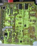
Here comes the photos of the board. Tried to be with as high as possible resolution.
My observations/conclusions so far are:
1- The board was detached from alu cover when washed.
2- 1st hypotheses: The most reasonable theory is the small metal pieces in earlier pictures must be released from the board (not washed away from the housing into board compartment).
3- Independent where they come from, having so many tiny metal parts washed from the board may have caused the sporadic short circuits suggested by MotoScan log-files.
4- Pls note the yellowish/orange colored areas which is a thin-film like dry residuals everywhere covering 4/5th of the surface from bottom. A lot of the dry film been washed away but still you can find (a lot of them) between components feet soldered to the board. (especially the largest IC component).
5- Even if the film should not be conductive itself, it can bind and hold metal pieces making the short circuits.
6- With so many small metal parts loose in the break fluid , it could be these which made short circuits on the board.

Now I am doing following, cm by cm:
A- I am checking the board for possible anomalies (burned components, burned spots, lose feet/connections etc. by zooming the taken photos. The microscope has not arrived yet :-(
B- I focus the search more on the bottom side of the board (both sides). The reason is if above theory is correct, small metal parts should covering the board from bottom, thus more risk for problems down there. But anywhere with small space (like between components feet) is a potential problem area.
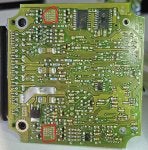
C- There is two specific areas (red-square) where could show missing or lose solder points to be repaired. What do you see there at the small holes? When the microscope available these could be easily determined.
D- The other marked (arrows) shows the yellow/orange residual between feet.

Kind regards
Farugh
 

Attachments

Hi Cefoul,
Here comes the photos of the board. Tried to be with as high as possible resolution.
My observations/conclusions so far are:
1- The board was detached from alu cover when washed.
2- 1st hypotheses: The most reasonable theory is the small metal pieces in earlier pictures must be released from the board (not washed away from the housing into board compartment).
3- Independent where they come from, having so many tiny metal parts washed from the board may have caused the sporadic short circuits suggested by MotoScan log-files.
4- Pls note the yellowish/orange colored areas which is a thin-film like dry residuals everywhere covering 4/5th of the surface from bottom. A lot of the dry film been washed away but still you can find (a lot of them) between components feet soldered to the board. (especially the largest IC component).
5- Even if the film should not be conductive itself, it can bind and hold metal pieces making the short circuits.
6- With so many small metal parts loose in the break fluid , it could be these which made short circuits on the board.

Now I am doing following, cm by cm:
A- I am checking the board for possible anomalies (burned components, burned spots, lose feet/connections etc. by zooming the taken photos. The microscope has not arrived yet :-(
B- I focus the search more on the bottom side of the board (both sides). The reason is if above theory is correct, small metal parts should covering the board from bottom, thus more risk for problems down there. But anywhere with small space (like between components feet) is a potential problem area.
C- There is two specific areas (red-square) where could show missing or lose solder points to be repaired. What do you see there at the small holes? When the microscope available these could be easily determined.
D- The other marked (arrows) shows the yellow/orange residual between feet.

Kind regards
Farugh
The yellow residue is just going to be varnish used to seal the board. Don't worry about that.
The area in the red squares looks like dry solder joints and the things in the center of the holes will be the pins that should be soldered to the board.
 
The yellow residue is just going to be varnish used to seal the board. Don't worry about that.
The area in the red squares looks like dry solder joints and the things in the center of the holes will be the pins that should be soldered to the board.
Thanks Wazza!,
Agree about the dry solder joints. That is my impression too.
About the yellow residue, if that is varnish it must been solved in the break fluid because they are found, with a sharp boarder, only in area from bottom to ca. 2 cm from the top.
You can find examples of lose flakes in this photo on black wires marked red.
This theory means, the protection is solved and gone anyways and the small metal pieces could create short circuits.
However the dry solder points are the prime suspects.

Kind regards
Image
 
61 - 80 of 143 Posts