BMW Luxury Touring Community banner

Integral ABS brakes diagram

44K views 142 replies 18 participants last post by  Riccardo71  
#1 ·
Hello everybody,

Considering the many threads about the Integral brake system of the K1200 LT, and not wanting to be caught off my guard by a failure, I would be interessed to understand how it works.
Question has anyone a diagram or a technical description explaining the principles of this system and the fonctions of the different components.

Thank you

Bruno
 
#2 ·
Bonjuor

Here is BMW's explanation of the system. The most important thing you can do is follow the brake fluid flush requirements. Annual on the wheel circuits and every two years on the control circuits. I have disassembled failed units and know pretty much what is going on inside.


These photos should give you an idea why the flush is so important.
 

Attachments

#9 ·
. I have disassembled failed units and know pretty much what is going on inside.
So,
If a failed unit is removed and repaired (or replaced)
Is it possible for a mear mortal to bleed the entire system and get the brake system working properly?
or is a visit to the dealer necessary?

I thought one of the important things was to NEVER get air in the unit... or a special tool/procedure etc. would be necessary... :confused:

ps
thanks for the reply on my other post/thread.
 
#4 ·
+1 on Thanks for the article - I hadn't seen that before.

In the article it said: "You will find the figures mentioned in this article in the German issue of ATZ 3/01 beginning on page 200."
 
This post has been deleted
#6 ·
I too was wanting to see the full details a while back. I went to the "ATZ Worldwide" website, you need to pay to get the full article. As an aside, I have the factory test documentation for the pre-delivery braking system checks on my '05 (all in German). I might ask someone at my workplace to translate it. Plenty of people have asked why BMW have elected to use such an intricate iABS system, but when the tech article is digested you can see they have attempted to control the wheels to that critical point between locking and not being locked, unlike car ABS systems which actually lock and release the wheels, hence the complexity of the control system (and the braking modulator).
 
#7 ·
I have the factory test documentation for the pre-delivery braking system checks on my '05 (all in German).

K100 DENIS,

Could you please copy this documentation.
Even in german, it could help to understand how it works.

Thank you

Bruno
 
#14 ·
John,

Just pull the output ports where the outgoing lines were. They have a long fine filter on them and that will give you an idea of the internal condition.
 
#16 · (Edited)
Found a burned section in the circuit board...
any idea if this burned section controls the servo to the front or both?

I am thinking that was the problem... the screens for the input and output looked fine.
however the brake fluid looked like a fine Colombian coffee.. :(


Anyway, I decided to remove the entire system. The brakes in the front feel great when I was done..
That is, until the right side rubber hose ruptured.. :rolleyes:
so, I will be ordering SS lines for both front and back.

They are the stock lines (2002) so It's about time to replace them anyway... actually glad it broke now and not in east bumphuck...

concerning the burned section on the board, My brake lights and speedo were working previous... so I think I will be OK plugging it back in.


burned section is top left hand corner.... click on it to enlarge pic.
 

Attachments

#17 ·
That would be the driver chip for the Front circuit pump. I had a board with some of those but I had sent it to a guy in Holland to fix his unit. Most likely cause was crud in the pump that stalled the motor and burned out the chip.
 
#18 ·
. Most likely cause was crud in the pump that stalled the motor and burned out the chip.
Yep,

I took apart the abs/servo assist control unit.. and that side (front) was very dirty.... also the motor on that side was dead... I reckon when the pump was getting tight it took out the motor and the chip.....

the other motor spins fine with 12v

Oh well... it's all in the garbage can now... waiting for my Galfer SS lines.

thanks for the help (again)

and sorry Bruno for hijacking your thread.... ;)
 
#25 ·
Maybe this will help. Each version is just a bit different even on LTs. The tiny pin with the spring is what pushes against a ball to seal the open loop fluid pressure loop and force the pressure out to the caliper. The Solenoid and armature is what evokes the ABS function to remove the pin from the ball.
173385


173386
 
#27 ·
I got it all back together with the spring and nipple in the top opening, and it all worked. Servo, ABS and residual braking all okay. Then the other day, I pushed the bike off the stand and the front brake barely stopped the bike.
Lots of investigation later, I conclude that the one-way valve on the outlet of the front pump is not working. Physically, where are these valves? Anyone got any idea.

Smiffy

(The symptoms are, with the ignition off, the front brake lever comes all the way back but the bike can still be pushed. If the ignition is on and the brake lever is pulled back the brake bites, if I then switch the ignition off, the lever comes back and the brake releases. If I do the same with the back brake, it works with the ignition off, and on and off again.)
 
#28 ·
The only valve in the wheel circuit is the one circled in red in post #25. But then I looked at my diagram and it shows a check valve after the pump. I suspect it is part of the pumps output port. It is open until you apply pressure in the control circuit to push it closed. Not sure why the lever is going all the way in with the key off. Do you get a very short movement of the lever with the key on?

This diagram may help you understand what is going on inside normally.

Image
 
#29 ·
Yes, short movement with ignition on.
There is no valve on the outlets of the pump, you can look in and see the pump rotor.
I think it must be in the part into which the brake pipe fits. This has a filter at the bottom which sits in the pump outlet chamber, a hole half way up which connects to the chamber behind the pistons (and also the pressure sensor) and at the top fits the brake pipe to the calipers. I'll try swapping that part front to rear and see if the problem moves to the rear circuit.
Thanks for the diagram.
 
#30 ·
The one-way valve does appear to be in that tube, but swapping them over made no difference.

With the top off the reservoirs, with the ignition on, pull the brake lever and the pump starts running, as I pull the lever, the piston (the shiny part in the red ring in your picture) moves a little and the lever stiffens as the brakes bite. When I turn off the ignition, the lever comes back to the bars and the piston moves forwards (to the left of the bike). When I release the lever the piston goes back.

With the ignition off, as I pull the lever the piston moves forwards but I feel no resistance until it is all the way forward. If I press the back brake as the piston moves forward I feel more resistance and the brake is applied.

It's as if there is some other way that the pressure in the caliper circuit is being dumped back to the reservoir. But I can't see any passages that come away from the caliper circuit other than from the pump and to the area that the piston goes into.

I have had it all apart again, put it back together and the behavior above is still the same except for one time when the lever held it's position when the ignition was turned off.

In the end I put it all back together so I could see how much actual braking I was getting with the ignition off.
On a medium downhill slope I let it build up speed to about 5mph then gently pulled the brake lever, I got a bit of braking, then a bit more, then a bit more (still not much though) then pulled it a little further and it reverted to the minimum braking I felt at first. Pulling the lever more made no difference. This was repeatable.

The problem MUST be in the back (left side on bike) block as the caliper circuit does not go anywhere else, So my next plan is to rebuild it using a different one of those.

Any thoughts?

Smiffy
 
#31 ·
Since the input is isolated the fluid movement that allows the lever to go to the bars is associated with the objects circled in blue. The only path for that fluid is in the primary input piston and the integral input piston on the other circuit. Now there are two pressure relief valves that are on the input side that could be causing this issue. They are the black domes you see on the ABS unit. Why they are letting the lever go to the bars is beyond me, but it is worth looking at it.

Image
 
#33 ·
OK. Now I see how you are observing this. Interesting. I suspect that that piston is free to move that far when there is no back pressure from the pump but not sure why. I will have to dig one of my units and see if I can move it that far by hand.

In looking at the videos, I see the rear piston move slightly when you are applying the front (integral) but I do not see the front move when you are applying the rear. There is something wrong in the integral circuits blocking movement in the front circuit with and input from the rear. That may mean a seal is bad internally.
 
#35 ·
OK. Now I see how you are observing this. Interesting. I suspect that that piston is free to move that far when there is no back pressure from the pump but not sure why. I will have to dig one of my units and see if I can move it that far by hand.
I have just been experimenting using the spare back case (left side on bike) and the intermediate section, no pumps fitted and using the armatures to push the "pistons". I held the piston all the way in, dribbled fluid into the outlet then as it filled with fluid allowed the piston to come out. When the fluid drained away suddenly, the "piston" was still pushed in well past the window, so the range of movement in the video with the ignition off, the output circuit won't hold any pressure. So look at a pump again, if I dribble fluid into the outlet holes it drains through straight away. None of it makes any sense.

I also looked at the pressure relief valves on the spare, they are just pistons with springs behind them, probably there to absorb some of the kick-back when the ABS activates the solenoids.
 
#38 ·
hello,

It's always sad to not have any news after spending some time to figure out what could be the issue and how to help with so few information.

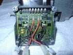
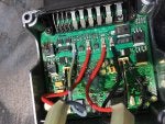
Anyway, for those who can be interested, I try to show how the control valve works in these I-ABS units and the dependency between the 2 separate fluid circuits: the one from the brake lever, in blue colour, and the one to the caliper, in yellow colour.

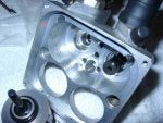
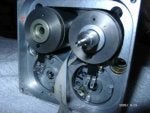
The main acting component is a small ball in front of the Control Piston ( in purple below). This ball split the whole area housing the failsave piston in 2 chambers.
I will explain later what is the role of the failsave piston.

1/ When the system is in standby mode, no brake activated, the gap between the 2 chambers is large and the pressure of the fluid is equal in both side (in yellow).

Image


2/ When the brake is pulled, the blue liquid will move the control piston, thus pushing the purple ball and reducing the gap between the 2 chambers.
At the same time the electric pump will raise up the pressure to the caliper and the green ball (a valve in the outlet port) will prevent the fluid to go back to the reservoir.
Usually, the failsave piston will not move. Only 2 mm of movement of the Control Piston is enough to lock the wheel.

Image


The ABS function is accomplished by the electromagnetic field forcing the Control Piston to move back and forward. This will increase and decrease alternatively the gap between the purple ball and the failsave piston, reducing the pressure and then re-applying the pressure to the caliper.

3/ When the I-ABS unit fails, there is still the possibility to have some kind of brake, called by BMW Residual braking feature and based on the failsave piston (but for me it is a cruel "joke").
The pilot will pull the lever to increase the pressure in the control circuit. The blue fluid will move deeper the control piston, the purple ball will completely close the gap.
Because the electric pump is out of service, the pilot has to increase the pressure at the lever and this will finally move the failsave piston.
This is how the pressure rise up to the brake caliper, in red colour below.

Image


Because we are on a forum and I spend time to write this text and do these pictures I have to add 3 things:
  • Sorry for my bad English, I'm quite better in my native language.
  • You are free to copy and use these pictures as long as you don't make any money with them. (yes, I'm a dreamer)
  • I really hope someone will found some help with this thread

By now, have a good and safe ride.
Cheers,
 
#40 ·
Because we are on a forum and I spend time to write this text and do these pictures I have to add 3 things:
  • Sorry for my bad English, I'm quite better in my native language.
  • You are free to copy and use these pictures as long as you don't make any money with them. (yes, I'm a dreamer)
  • I really hope someone will found some help with this thread

By now, have a good and safe ride.
Cheers,
@Cefoul

Although I am not your target audience as I am an RT rider, I sure appreciate your making the effort to create the diagram and describe it's operation.

Thank you and ride safe -
Larry
 
#39 ·
Great, I got it all. Now I have to try to fix mine.
I collected 5 ABS 3 units.- 3 from BMW 1150 and 2 from k1200 LT, I'm not going to run out of parts, I have work for this winter.
In the meantime I ordered an emulator in Poland and I will mount it on my motorbike. I will give you my impressions.
 
#41 ·
Great, I got it all. Now I have to try to fix mine.
I collected 5 ABS 3 units.- 3 from BMW 1150 and 2 from k1200 LT, I'm not going to run out of parts
Hi Chris,

You can use a lot of the internal parts between the various models except for these 3 things which are specifics to each model (K1200LT, K1200RS/GT, R1150RT ....):

1/ The electronic board is specific to the model

2/ The pressure relief valve is colour coded. Even on the same model, the front and the rear units are sometimes different. I have seen blue, yellow, white, green colour dot on the top of the black cap.
These valves are used to stabilize the pressure created by the pilot when the brake lever is pulled.

Image


3/ The integral piston located in the first section of the unit. It depends if it is an Integral ABS or a Semi-Integral ABS.

Image


As long as you can order the correct seals (FPM) and replace all of them, and the capability to check the 4 internal pressure sensors (GS911 can do it), you might be able to rebuild a working unit.
These pressure sensors and the DC motors are the most problematic parts.
Some components on the main board can die, due to a problem with one or the 2 DC motors but it is more or less an easy fix.

Good luck,
 
#44 ·
Great info here, thanks everyone! I have just taken the abs unit out of my 03 LT, front system suspect with possible faulty motor according to diagnostic test. The filter was definitely very dirty.. as well as the reservoir for the front circuit. Does anyone have a diagram of which pins operate the motors? Would like to apply 12v to the front motor to see if it engages before I pull it apart.